PART 4 - Results
HOT WATER STORAGE STRATEGY IN INTERNAL COMBUSTION ENGINE
1st AREA: THERMAL MANAGEMENT
Abstract
This subject is linked to the previous one (oil strategies benefits). In this case, hot coolant storage was applied to the system in order to assess the fuel consumption gain. The storage tank was located downstream of the thermostat and upstream of the radiator with three valves to control the coolant flow. The place was chosen in order not to badly influence the cold start-up of the engine when the tank is at the ambient temperature. This strategy was applied on different driving cycles: the NEDC, WLTC, CADC (Urban and highway), and an in-house developed driving cycle (HDC). The ambient temperature was varied between -7°C to present the coldest winter and 20°C. The results of this study summarize the ability of the hot coolant storage strategy to reduce fuel consumption and shows the best driving cycle that needs to be applied and the influence of the different ambient temperatures.
Coolant circuit description and simulation results
An isolated volume of coolant was placed downstream of the thermostat and upstream of the radiator. This position was chosen to have the lesser impact of the additional volume on the first cold start-up of the engine. During the transient phase, the engine does not have to warm-up the storage volume while the thermostat blocks the way to the radiator, thus to the storage volume. Once the optimal temperature is reached, the thermostat opens the radiator branch, and then the hot water is stored in the specific tank before being cooled down by the radiator. The storage volume is controlled by three valves in addition to the thermostat as shown below.
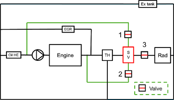
Schematic presentation of the hot coolant storage strategy
For the first start-up, the coolant in the storage volume is at the ambient temperature. With the thermostat closed, the storage volume is isolated from the engine and the latter works normally during the transient phase. It means that the coolant flows to the engine, then to the bypass branch and the EGR branch, before entering the oil heat exchanger and back to the pump. Once the optimal temperature of the engine is reached, the thermostat opens and hot coolant enters the radiator branch. The valve number 3 opens and closes with the thermostat. With the hot coolant entering the radiator branch, the storage volume starts to be filled with hot water. With the next cold start-up, hot coolant stored in the volume will be used to warm-up the engine. As the optimal temperature has not been reached yet the thermostat is closed, thus the valve number 3. Valves 1 and 2 are used as follows. If the temperature of the engine is lower than that of the storage volume and the thermostat is always closed (that means the optimal temperature is not reached yet, in this study it was set at 83°C), the valve 1 and 2 open and the hot coolant in the storage volume is sucked by the pump and pressurized and sent to the engine to warm it up. Once one of the two conditions is not met, the two valves close and the engine goes back to the traditional architecture until the optimal temperature is reached and the hot coolant is stored again. 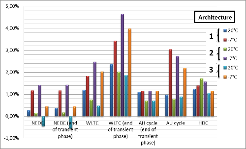
The first architecture proposed for the hot coolant strategy consists of the storage tank downstream of the thermostat and has the coolant flow that goes downstream of the oil heat exchanger. In order to have a better influence on the lubricant temperature, the outlet of the storage tank was proposed to be upstream of the oil heat exchanger. This is the second architecture. A third architecture was proposed, where the storage tank was placed upstream of the thermostat, in a way to be heated without any control. In the third architecture, the total volume of the engine’s coolant was raised. During the transient phase, the engine should heat the additional storage volume to reach its optimal temperature.
All architectures give the possibility to decrease the fuel consumption. The following graph sums up the different fuel consumption gain issued from this study.