PART 2 - Results
INFLUENCE OF ACTIVE COOLING THERMAL MANAGEMENT VALVE ON FUEL CONSUMPTION AND ENGINE WARM-UP
1st AREA: THERMAL MANAGEMENT
Abstract
Thermal management technologies are increasingly developed to lower fuel consumption and pollutant emissions whilst keeping the same driving and thermal comforts. This entails reducing warm-up time and friction losses without detriment to fuel consumption. A new technology for engine cooling systems named ACT valve (Active Cooling Thermal management valve) was developed by Mann+Hummel. It allows first to implement a no flow strategy to decrease the warm-up time and to enhance thermal comfort. It is also able to accurately control the coolant flow and temperature depending on engine operating load and speed, and so to decrease friction and heat losses. In order to quantify the fuel consumption potential, a complete engine simulation has been developed. Tests were also performed in the laboratory and on an engine bench enabled to tune the combustion and thermal parameters.
Component description
In most current architectures, the radiator branch on an engine is the only one to be controlled. This is done using a wax thermostat. The latter is a passive valve driven by the thermal expansion of a wax volume for the opening and by a spring for the closing. Depending on this wax composition, the opening temperature of the circuit can be tuned to one single value. Sometimes an electric heater is inserted on the wax volume to modify the opening temperature. A plane valve with a spring can be added to close the bypass branch when the radiator branch opens. This way, only 2 branches can be controlled and the coolant temperature can be controlled at only 3 to 4 set points with response time depending an coolant temperature.
The ACT valve has been developed to replace current passive wax-based thermostat with a temperature-driven, active multi-channel valve module. This new product is the result of an advanced engineering project that started in 2007. The first functional prototype was tested in 2009 and MANN+HUMMEL was awarded on the first serial production in 2010. The function of the part is to control the flow through all the external cooling circuits. The circuit control strategy is mainly defined by the customer’s specifications; MANN+HUMMEL often assist and support the development of the different flow strategies. The aim is to offer a solution that is flexible enough to fit with constrained packaging and able to integrate different strategies
Poppet valve and cam profile design
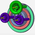
This innovation has been developed to address the issue: “what is the best plastic based solution for controlling the flow through several circuits with one single actuator while guaranteeing low leakage and progressiveness requirements? At the same time dealing with packaging constraints, plastic processing capabilities and cost issue?”. Finally, the retained solution is based on poppet valves as shutters for each branch to be controlled. The design is shown below. The valve lifts are managed directly by a plane cam with different tracks. The flow control strategy is directly implemented on the cam profile. This is done by fitting the track profile of the cam to match the different openings and closings needed. The local heights of the cam tracks manage the valve lifts.
Several strategies can be implemented to the cam. For example, after a no flow position, the cabin heater branch is open for the thermal comfort, then the bypass is open to increase the engine flow and finally the radiator branch is open when the bypass one is closed to regulate the temperature.
Several strategies can be implemented to the cam. For example, after a no flow position, the cabin heater branch is open for the thermal comfort, then the bypass is open to increase the engine flow and finally the radiator branch is open when the bypass one is closed to regulate the temperature.
Component behaviour studies
The model is used in order to evaluate the impact of different cooling strategies on the fuel consumption and therefore on CO2 emissions. The standard cooling configuration on the engine behaves as follows: the cabin heater branch is always opened and a double effect thermostat is used in order to open the radiator branch while closing the by-pass. Two different ACT valve concepts are proposed and simulated; they are named ACT_A and ACT_B. ACT_A: zero flow is possible; the cabin heater opens first and stays always open. The by-pass opens at 80°C and the radiator branch opens to regulate the water temperature at 105°C. ACT_B: the by-pass is opened for cold temperatures, and then it’s closed when the cabin heater branch opens. The radiator branch opens to regulate the water temperature at 105°C.
The different ACT valves as well as the standard engine thermostat outlet are simulated for 5 different driving cycles: NEDC, WLTP, Artemis Urban, Artemis Road, and Artemis Highway. Each simulation started at a stabilized temperature of 20°C.
The evolution of the coolant temperature is presented below. The zero flow strategy leads to a quicker rise of the temperature of the engine: the volume of water to warm up is smaller.
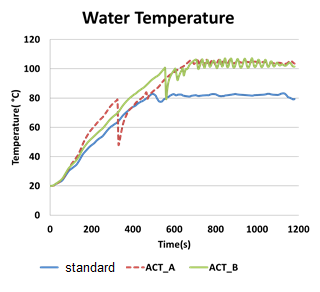
Water temperature evolution on NEDC
However, as soon as the heater branch is engaged, a decrease of temperature is observed due to the cold water now moving into the engine. One drawback of the zero flow strategy is the uncertainty of the temperature measurement at the ACT valve location because the sensed temperature can actually be significantly lower than the temperature inside the cylinder head; which is why the bypass branch is opened at 80°C for security reasons. The B type architecture leads to a water temperature between the two other cases (ACT_A and standard configuration). On the other hand, and because there is always a flow present (no zero flow), the confidence of the temperature measurement is good enough to wait until 100°C before opening the branches. Water temperature rises slower than the type A solution, but is actually higher for the second half of the warm-up phase.
The reduction of fuel consumption is linked to the reduction of the dissipated heat losses thanks to a quicker warm-up and higher regulation temperature. The CO2 savings (between 1 and 2%) are higher under “urban” conditions (lighter loads). On the other hand, for the highway cycle, the temperature rise is quicker (higher load operation). A gain of 0.5% is obtained and mainly due to the regulation at 105°C. For the considered cooling circuit in this application, the type A strategy gives better results during warm-up (both with WLTC and NEDC in urban configuration). The type B could however be interesting for other cooling circuits (different pump, oil cooler in series with the engine…).
The reduction of fuel consumption is linked to the reduction of the dissipated heat losses thanks to a quicker warm-up and higher regulation temperature. The CO2 savings (between 1 and 2%) are higher under “urban” conditions (lighter loads). On the other hand, for the highway cycle, the temperature rise is quicker (higher load operation). A gain of 0.5% is obtained and mainly due to the regulation at 105°C. For the considered cooling circuit in this application, the type A strategy gives better results during warm-up (both with WLTC and NEDC in urban configuration). The type B could however be interesting for other cooling circuits (different pump, oil cooler in series with the engine…).