PART 1 - Results


NODAL MODELLING FOR ADVANCED THERMAL-MANAGEMENT OF INTERNAL COMBUSTION ENGINE

1st AREA: THERMAL MANAGEMENT

Abstract


The evolution of temperatures in internal combustion engines during cold start is quite important. This greatly affects fuel consumption and vehicle emissions. An advanced thermal management model was developed and used on an automotive Diesel engine in order to determine the evolution of the different temperatures during warm-up stage.

The work focuses on the complete description of the engine components, coolant circuit, and lubricant circuit. The objective is to calculate the heat exchanges between the thermal masses of sub-models (cylinder head, engine block, pistons, oil sump…) and the fluids. Experiments on an engine were undertaken in order to calibrate the model (heat release, friction losses…), but also to obtain the temperature evolutions during transient stage. These last results were used in order to validate the model.

This approach makes it possible to determine the coolant and oil temperature evolution with a minimum of nodes and a relatively short calculation time. The evolution of the coolant temperature in a vehicle during a NEDC cycle with a cold start was studied. A good agreement was obtained. Finally, the model was used in order to study the possibilities to reduce the vehicle mass by a reduction of the engine mass.
 

Model description


In order to establish the new model and study the influence of the different parameters, a four cylinder turbo-Diesel engine is used. It was equipped with a common rail fuel injection system, a high EGR loop, a turbocharger with a VGT and a charge air cooler.

The simulation code is divided into two distinctive models. On the one hand a high-frequency (HF) code is used. It describes the air circuits of the engine (inlet and exhaust), and computes the injection and combustion processes as well as the wall heat losses. This model has been calibrated with tests performed on the engine test-bench. On the other hand, the nodal model is a low-frequency (LF) code which aims to describe the thermal flux of the engine. Thus, it includes both lubricant and coolant circuits (specifications, pumps, lubricant/coolant exchanger, tanks…) as well as some external components such as the radiator and the heater. Yet its main asset lies in the 91 masses representing the engine (total of 120kg) and the thermal convections or conductions linked. Each mass has its own specifications (weight, volume, material, heat transfer coefficients) and its own external thermal network. Finally the nodal model also includes a set of parameters to define the geometric data of the engine, the road cycle, ambient conditions, and the vehicle parameters.


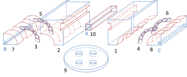
Exploded view of the 10 masses and 3 coolant nodes representing the engine head above one cylinder
The first stage of building a nodal model is to divide the components into a finite number of isotherm physical volumes. For internal combustion engines, the elements to be discretised are the metal masses, the coolant circuit and the lubricant circuit. The connection between two nodes is different, whether it is between two metal masses or between a metal mass and a fluid. The discretisation of the internal combustion engine cannot yet be done solely with the above equations. Two other guidelines are needed for a proper discretisation. First, the division of the masses has to be performed by taking into account the places with strong spatial and temporal gradients. Then, the geometrical design of the engine must be simplified. Indeed, the precise modelling of the actual volumes is very challenging and often requires data that is either inaccessible or unknown (particularly in the development stage of an engine). However, the simplifications must respect the global mass and volume of real elements as well as the contact surfaces between nodes.

For example, the bottom blocks of the head include the inlet and exhaust pipes, the valves, and parts of the coolant circuit. Many elements must be taken into account for the heat balance: heat from the combustion, friction power from camshaft, and convection with the air circuit, the coolant circuit and the burned gases. This block is divided into four main parts, one for each cylinder, which are themselves divided into ten mass nodes and three coolant nodes. The following figure shows the rough geometrical layout of the ten masses with its coolant circuit for a central cylinder (meaning cylinder number 2 or 3 for the inline-4 cylinder engine).

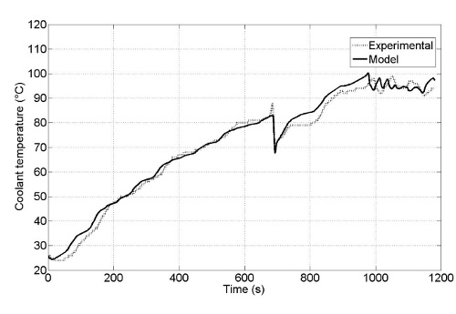
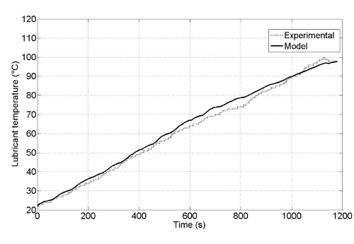
Engine experimental tests


In order to validate the new model, different tests were run with the internal combustion engine connected to the dynamometer test bench. The validation is performed during a warm-up phase. Different engine operation points were chosen. The test consists of running the engine at a specific operating point with all the fluids (air, coolant, and lubricant) initially at ambient temperature. The different engine parameters are recorded as a function of time. For example, the results obtained for an engine rotational speed of 2200 rpm and an engine torque of 60 Nm are analysed in the graph below. For this configuration, the temperature is regulated at 105°C. A good agreement is obtained between the experimental and model results for the coolant temperature evolution, but also during the regulation at final temperature. Regarding the lubricant temperature, the results are acceptable even if the curves are not as close as to the coolant. Then, it is possible to obtain a correct evolution of the temperature during warm-up phase.
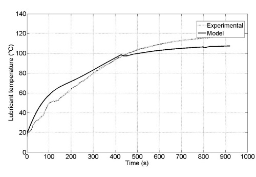
Evolution of the coolant and lubricant temperatures for N = 2200 rpm and Torque = 60 N m.

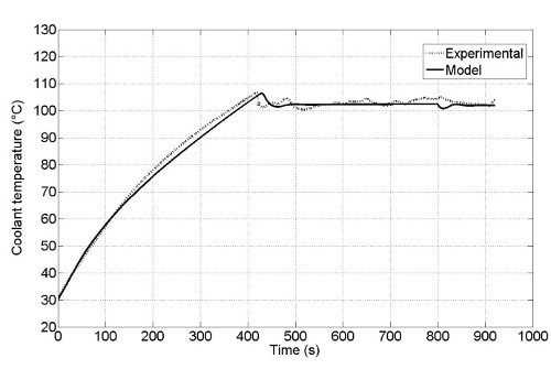
Vehicle experimental tests


Experiments were also conducted on a chassis dynamometer where the tested vehicle was a C4 Cactus with common-rail Diesel injection. For this experimental setup, the vehicle wheels were removed and replaced with electric motors (as depicted below). Sensors have been added on the coolant and lubricant circuits in order to record the evolution of the temperatures. During the test, the objective of the driver was to reproduce the NEDC. At the beginning, all temperatures are equal to the ambient temperature. Moreover, modifications were made on the simulation code in order to include the car radiator and the thermostat strategy.
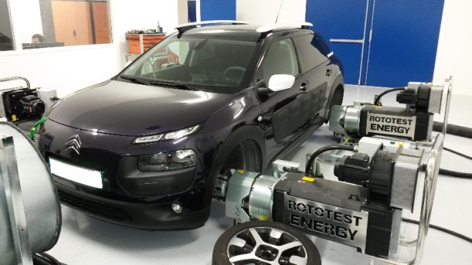
Vehicle installed on the test bench with instrumentation
The coolant temperature is analysed. During the warm-up stage, a good agreement is obtained between the experimental result and the numerical one, as depicted below. Shortly before 700 seconds, the thermostat opens to allow coolant to go to the car radiator. This occurs at a temperature around 83°C. At this moment, the coolant initially in the car radiator and in pipes is going into the engine. However this coolant is “cold” and as a consequence the engine temperature decreases. This phenomenon is fairly well reproduced by the simulation. Subsequently, this coolant also heats up until it reaches the regulation value, around 95°C. The model also allows obtaining a correct evolution of the lubricant temperature (as depicted below). These results confirm the ability of the model to adequately determine the evolution of temperatures during the warm-up stage of an engine in vehicle under-hood.
Evolution of the coolant and lubricant temperatures of the vehicle during a NEDC cycle
Published on January 17, 2018 Updated on February 1, 2018